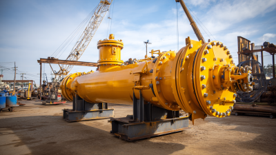
You know, in oil, gas, and chemical plants, a Three Phase Separator is basically the unsung hero that turns a wild, turbulent well stream into three simpler, manageable outputs. It’s like this vessel that gets gas, hydrocarbon liquids, and produced water all coming in together. Inside, there’s a clever little inlet diverter that slows things down a bit, giving gravity a chance to do its thing—dropping heavy water to the bottom and letting lighter oils float up. The gas naturally rises to the top, and tiny droplets of liquid settle through calmer zones. Sometimes, coalescing pads are added to catch even finer droplets, but they can’t fix poor design choices. Small details really matter here—like a sudden drop in pressure can cause foaming, carryover, or make level control go all wonky. It’s a delicate balance.
Ken Arnold, who's a well-known production-facilities engineer and co-authored Surface Production Operations, sums it up nicely: “The purpose of a separator is to split the well stream into its three phases.” Pretty straightforward, right? But in reality, how well this works depends on both the equipment itself and how you operate it. Operators keep an eye on pressure, interface level, temperature, and flow rates. Instruments give you useful signals, but you can’t skip field checks—that’s still super important. Especially since a separator sized for average flow might choke or struggle during slugging, startup, or when the fluid properties change. Those are tricky spots that need attention.
Engineers look at things like retention time, droplet sizes, emulsion behavior, and relief protections before choosing internal components. It’s not just a giant tank with three nozzles—it's a carefully controlled boundary that keeps things running smoothly. This guide will walk you through what the equipment does, how separation actually works, common setups, and practical tips for checking if everything’s functioning right. Plus, it points out where simple diagrams can be misleading—because real fluids don’t always play by the rules. With a bit of field experience, solid calculations, and regular inspections, a good Three Phase Separator can safeguard your compressors, pumps, and treatment units—making everything safer and more reliable in the long run.

A three-phase separator is a pressure vessel designed to divide a mixed production stream into gas, liquid hydrocarbon, and water. Its purpose is practical: protect downstream equipment, improve measurement, and prepare each phase for further treatment. The inlet slows and spreads the flow, reducing turbulence. Gas rises, while heavier liquids settle. Inside, gravity, residence time, and controlled interfaces do most of the work. Mist eliminators capture small liquid droplets from the gas. Weirs or level controls help direct the liquid outlets. The vessel may be horizontal or vertical, depending on flow rate, available space, and liquid behavior. It is not merely a large tank.
During operation, instruments monitor pressure, liquid levels, and the oil-water boundary. Operators adjust valves when foaming, emulsions, or changing flow conditions disturb separation. A clear interface is not guaranteed. That matters. Excessive inlet velocity can carry water into the oil outlet or liquid into the gas stream. Poor temperature control may increase viscosity and slow settling. Engineers therefore size the vessel using fluid properties, droplet size, retention time, and operating pressure. Field inspection remains important because deposits, corrosion, and faulty level signals can reduce performance. A separator can meet its design target, yet still need adjustment as the process changes.
| Dimension | Definition or Data | How It Works or Why It Matters |
|---|---|---|
| Definition | A three-phase separator is a process vessel designed to separate a mixed stream into gas, hydrocarbon liquid, and water. | Separation is achieved primarily through gravity, residence time, controlled flow, and differences in density. |
| Separated Phases | Gas is the lightest phase; hydrocarbon liquid, such as crude oil or condensate, is generally lighter than water; water is normally the densest phase. | The density difference allows the phases to form separate zones inside the vessel when turbulence is sufficiently reduced. |
| Typical Flow Sequence | Inlet mixture → inlet device → gas disengagement → liquid separation → oil–water interface separation → individual outlets. | Each stage reduces entrainment and improves the quality of the gas, hydrocarbon-liquid, and water outlets. |
| Inlet Device | An inlet diverter, diffuser, or cyclonic inlet device reduces momentum and distributes the incoming stream. | Reducing inlet velocity helps prevent excessive turbulence, foaming, and re-entrainment of liquid into the gas outlet. |
| Gas Separation Zone | The upper section of the vessel provides space for gas to disengage from the liquid. | Gas rises toward the gas outlet while entrained liquid droplets fall back into the liquid section. |
| Demister or Mist Extractor | A mesh pad, vane pack, or similar mist-elimination device removes fine liquid droplets from the gas stream. | It improves gas quality by causing droplets to coalesce and drain back into the vessel. Excessive liquid loading can cause carryover or pressure drop. |
| Liquid Separation Zone | The liquid section provides sufficient residence time for hydrocarbon liquid and water to separate by gravity. | Large droplets settle or rise more readily than small droplets. Coalescing devices may be used to improve separation. |
| Oil–Water Interface | The interface is the boundary between the hydrocarbon-liquid layer and the water layer. | Interface level control is essential for maintaining the correct volume of each liquid phase and preventing water in the oil outlet or oil in the water outlet. |
| Residence Time | Residence time is the average period the fluid remains in the vessel before leaving. | More residence time generally improves gravity separation, although the required value depends on flow rate, viscosity, droplet size, emulsion behavior, and operating conditions. |
| Pressure Control | Vessel pressure is controlled through the gas outlet using a pressure-control valve or equivalent control system. | Stable pressure supports consistent gas flow and helps maintain predictable vapor–liquid equilibrium and separation performance. |
| Level Control | Total liquid level is controlled at the liquid outlet, while the oil–water interface is controlled at the water outlet or by an internal control arrangement. | Correct level control prevents gas blow-by through liquid outlets and limits liquid carryover through the gas outlet. |
| Common Vessel Orientation | Separators may be horizontal or vertical. | Horizontal vessels generally provide a larger interface area and longer liquid residence path. Vertical vessels can be useful where floor space is limited or where high gas volumes require additional disengagement height. |
| Key Design Variables | Gas and liquid flow rates, operating pressure, operating temperature, fluid densities, viscosity, droplet size, emulsion tendency, and allowable outlet carryover. | These variables determine vessel dimensions, internal equipment, residence time, control requirements, and expected separation efficiency. |
| Typical Internal Components | Inlet device, baffles, weirs, calming plates, coalescing elements, mist extractor, vortex breaker, and level-control arrangements. | Internal components manage flow distribution, stabilize liquid layers, reduce turbulence, and protect downstream equipment. |
| Gas Outlet Product | Gas with reduced entrained hydrocarbon and water droplets. | The separated gas may be routed for compression, treatment, measurement, fuel use, or further processing, depending on its composition and required specification. |
| Hydrocarbon-Liquid Outlet Product | Hydrocarbon liquid with reduced free water and gas content. | Further treatment may be required when the liquid contains emulsified water, dissolved gas, solids, or contaminants. |
| Water Outlet Product | Water with reduced free hydrocarbon content. | Additional treatment may be necessary before reuse, discharge, injection, or transfer, depending on applicable operating requirements. |
| Solids Management | Some separators include a drain, sand-jetting arrangement, or solids-handling section. | Removing accumulated sand and other solids helps preserve effective volume, avoid blockage, and maintain reliable level measurements. |
| Performance Limitations | Very small droplets, stable emulsions, high viscosity, foaming, excessive turbulence, and rapid flow changes can reduce separation performance. | Additional equipment, such as coalescers, hydrocyclones, heat treatment, or chemical treatment, may be required for difficult services. |
| Safety and Protection | Typical protection includes pressure-relief devices, high- and low-level alarms, shutdown functions, drains, vents, and inspection provisions. | These systems help protect personnel and equipment from overpressure, liquid carryover, gas blow-by, loss of containment, and abnormal operating conditions. |
Summary: A three-phase separator uses controlled flow and density differences to divide a mixed stream into gas, hydrocarbon liquid, and water. Effective operation depends on adequate residence time, stable pressure and level control, suitable internal devices, and proper management of emulsions, foam, solids, and flow fluctuations.
It is a pressure vessel that separates gas, oil, and water. Gravity does most of the work. Not magic.
The mixture enters through an inlet nozzle at high velocity. An inlet diverter reduces momentum and spreads the flow.
Gas rises, water settles, and oil forms a middle layer. Temperature and density can shift these layers.
Important parts include the shell, inlet diverter, baffles, weir, water boot, and vortex breakers. Their positions matter.
A mist eliminator removes fine liquid droplets from the gas. It may use wire mesh or vane elements. Clean surfaces matter.
Level instruments monitor the oil-water interface and adjust external control valves. A weir helps maintain oil level.
Excessive turbulence can carry water into the oil outlet or liquid into the gas line. Emulsions may also slow separation.
Inspect drains, access points, supports, demister condition, and vortex breakers. Look for sand or wax in quiet corners. A drawing is not proof.
A Three Phase Separator is a pressure vessel designed to divide a combined stream of gas, oil, and water into three separate phases. It is widely used in petroleum, natural gas, chemical, and process industries to improve fluid quality and support efficient downstream operations. The vessel commonly includes an inlet device, a settling chamber, baffles or coalescing elements, a mist extractor, liquid-level controls, and separate outlets for gas, oil, and water. These internal components reduce turbulence and provide enough residence time for the phases to separate according to their density and physical properties.
As the mixed fluid enters, its velocity decreases, allowing gas to rise, water to settle, and oil to remain between them. The gas leaves through the upper outlet after passing through a mist-removal section, while oil and water are discharged through controlled liquid outlets. Horizontal, vertical, and spherical designs are selected according to capacity, space, and process requirements. Separation efficiency depends on pressure, temperature, flow rate, residence time, fluid viscosity, droplet size, emulsion strength, and accurate control of interface levels.